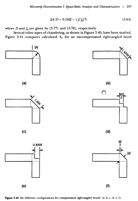
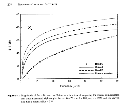
I would like to change a PCB to add a (not straight angle) 90° curve in a 900MHz signal path.
From my understanding my PCB designer is simply using the correct impedance, routing the signal on the top layer and using the ground plane below as a return path.
From his experience it would be advisable to simply use a right angle connector outside of the PCB, and doing another 90° curve inside the PCB is a bad idea (we already have one, but at -10 dBm).
I would like to understand what kind of problems another 90° in-pcb signal path curve would bring (only signal attenuation? Or distortion as well?) and if that depends on the power of the signal doing the curve (eg. would a -10 dBm signal be less affected than a 20 dBm one?).
Thank you.


