0
\$\begingroup\$

I am trying to design in VHDL a RAM model. The idea is to being able to implement the different load instructions (lb, lh and lw) present in the RISCV ISA (the overall project is to design a complete CPU).

At the end, I would like to being able to run this kind of instructions on this CPU:

uint8_t byte_var = 0x41;
uint16_t halfword_var = 0xa25c;
uint32_t word_var = 0x12345678;

This is why I would like this RAM to provide 8-bit, 16-bit and 32-bit readings/writings.

This is purely for learning purposes and my goal is to design it from scratch (not using any already existing IP) to understand how it internally works. At end, being able to make it work in simulation is enough for me, I do not intend to implement it in a FPGA, at least for now.

I tried different designs but I don't know if there are good or bad.

First Design:

The output is a 32-bit signal. In case of a 8-bit or 16-bit writing, this signal is padded with leading 0s to get the expected 32-bit output width.

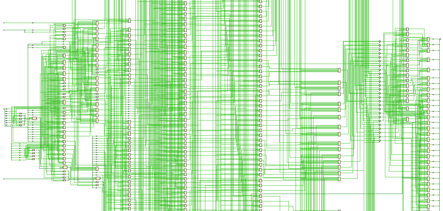
It seems to be working, however I am wondering if I am not over-complicating the RAM model. The schematic resulting from the synthesis looks quite complex to me, but I am not really familiar with usual schematics so perhaps it is actually fine.

Please find below this first design:

library IEEE;
use IEEE.STD_LOGIC_1164.ALL;
use IEEE.NUMERIC_STD.ALL;


entity data_ram is
    port(
        clk             : in std_logic;
        addr            : in std_logic_vector(31 downto 0);
        access_width    : in std_logic_vector(1 downto 0);       -- "00" : illegal; "01" : 8-bit; "10" : 16-bit; "11" : 32-bit
        write_enable    : in std_logic;
        data_in         : in std_logic_vector(31 downto 0);
        
        data_out        : out std_logic_vector(31 downto 0)
    );
end data_ram;


architecture Behavioral of data_ram is
    constant RAM_SIZE_BYTES : integer := 32;
    type DATA_RAM_MEMORY_ARRAY_t is array (0 to RAM_SIZE_BYTES-1) of std_logic_vector(7 downto 0);
    signal memory : DATA_RAM_MEMORY_ARRAY_t;
    
begin

    process(clk)
        variable index     : integer;
    begin
        index      := to_integer(unsigned(addr));
        
        if rising_edge(clk) then
            if(index < RAM_SIZE_BYTES) then
            
                case access_width is
                    when "00" => -- illegal value, do not write and output 0xffffffff
                        data_out <= (others => '1');
                    when "01" =>    -- 8-bit
                        data_out <= (31 downto 8 => '0') & memory(index);
                        if(write_enable = '1') then
                            memory(index) <= data_in(7 downto 0);
                        end if;
                    when "10" =>    -- 16-bit
                        data_out <= (31 downto 16 => '0') & memory(index+1) & memory(index);
                        if(write_enable = '1') then
                            memory(index) <= data_in(7 downto 0);
                            memory(index+1) <= data_in(15 downto 8);
                        end if;
                    when others =>  -- 32-bit
                        data_out <= memory(index+3) & memory(index+2) & memory(index+1) & memory(index);
                        if(write_enable = '1') then
                            memory(index) <= data_in(7 downto 0);
                            memory(index+1) <= data_in(15 downto 8);
                            memory(index+2) <= data_in(23 downto 16);
                            memory(index+3) <= data_in(31 downto 24);
                        end if;
                end case;
                
                
            else
                data_out <= (others => '1');
            end if;
        end if;
    end process;

end Behavioral;

This works fine it simulation, but let's see the result given by the synthesis: Here is the schematic resulting from the synthesis: enter image description here enter image description here

enter image description here

enter image description here

This looks too complex for only 32 bytes of storage ! This design is probably bad, although it works in the ideal case. In the real case, we would probably face some timing issues ?

Second design:

As suggested in the answers, I switched to a 32-bit wide memory instead of a 8-bit wide one.

Please find below this new design:

library IEEE;
use IEEE.STD_LOGIC_1164.ALL;
use IEEE.NUMERIC_STD.ALL;


entity data_ram is
    port(
        clk             : in std_logic;
        addr            : in std_logic_vector(31 downto 0);
        access_width    : in std_logic_vector(1 downto 0);       -- "00" or "01" : 8-bit; "10" : 16-bit; "11" : 32-bit
        write_enable    : in std_logic;
        data_in         : in std_logic_vector(31 downto 0);
        
        data_out        : out std_logic_vector(31 downto 0)
    );
end data_ram;


architecture Behavioral of data_ram is
    constant RAM_SIZE_WORDS : integer := 8;
    type DATA_RAM_MEMORY_ARRAY_t is array (0 to RAM_SIZE_WORDS-1, 3 downto 0) of std_logic_vector(7 downto 0);
    signal memory : DATA_RAM_MEMORY_ARRAY_t;
    
begin

    process(clk)
        variable word_index     : integer;
        variable halfword_index : integer;
        variable byte_index     : integer;
    begin
        word_index      := to_integer(unsigned(addr(31 downto 2)));
        halfword_index  := to_integer(unsigned(addr(1 downto 0) and "10"));
        byte_index      := to_integer(unsigned(addr(1 downto 0)));
        
        if rising_edge(clk) then
            if(word_index < RAM_SIZE_WORDS) then
                case access_width is
                    when "10" =>    -- 16-bit
                        data_out <= (31 downto 16 => '0') & memory(word_index, halfword_index+1) & memory(word_index, halfword_index);
                        if(write_enable = '1') then
                            memory(word_index, halfword_index) <= data_in(7 downto 0);
                            memory(word_index, halfword_index+1) <= data_in(15 downto 8);
                        end if;
                    when "11" =>  -- 32-bit
                        data_out <= memory(word_index, 3) & memory(word_index, 2) & memory(word_index, 1) & memory(word_index, 0);
                        if(write_enable = '1') then
                            memory(word_index, halfword_index) <= data_in(7 downto 0);
                            memory(word_index, halfword_index+1) <= data_in(15 downto 8);
                            memory(word_index, halfword_index+2) <= data_in(23 downto 16);
                            memory(word_index, halfword_index+3) <= data_in(31 downto 24);
                        end if;
                    when others =>  -- 8-bit
                        data_out <= (31 downto 8 => '0') & memory(word_index, byte_index);
                        if(write_enable = '1') then
                            memory(word_index, byte_index) <= data_in(7 downto 0);
                        end if;
                end case;
                
                
            else
                data_out <= (others => '1');
            end if;
        end if;
    end process;

end Behavioral;

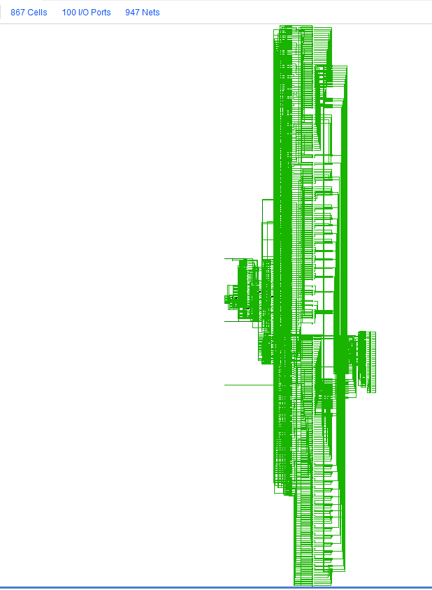
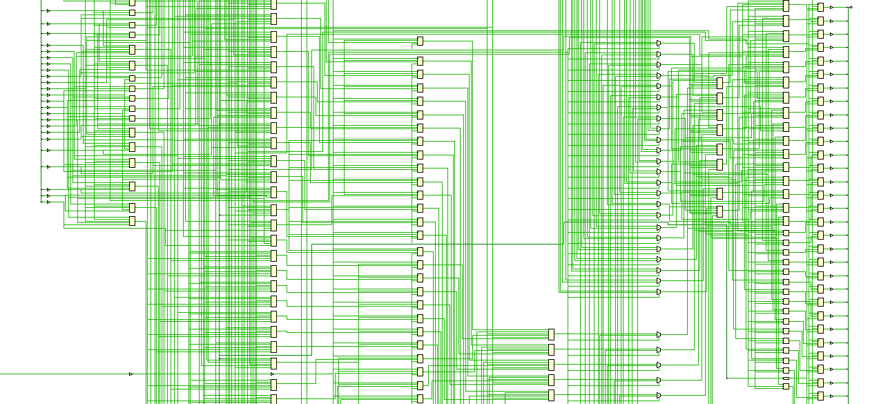
This design gives the same results in simulation than the previous one, but is more optimized:

enter image description here

enter image description here

enter image description here

But it still looks complex, right ? 867 cells are involved for still a 8 bytes storage.

Third design:

So I tried something different. Instead of accessing the data with several indexes, I now access a full word, whatever the desired reading/writing width is, and given the desired reading/writing width, I modify this word with bit masks, and then write back this entire modified word.

library IEEE;
use IEEE.STD_LOGIC_1164.ALL;
use IEEE.NUMERIC_STD.ALL;


entity data_ram is
    port(
        clk             : in std_logic;
        addr            : in std_logic_vector(31 downto 0);
        access_width    : in std_logic_vector(1 downto 0);       -- "00" or "01" : 8-bit; "10" : 16-bit; "11" : 32-bit
        write_enable    : in std_logic;
        data_in         : in std_logic_vector(31 downto 0);
        
        data_out        : out std_logic_vector(31 downto 0)
    );
end data_ram;


architecture Behavioral of data_ram is
    constant RAM_SIZE_WORDS : integer := 8;
    type DATA_RAM_MEMORY_ARRAY_t is array (0 to RAM_SIZE_WORDS-1) of std_logic_vector(31 downto 0);
    signal memory : DATA_RAM_MEMORY_ARRAY_t;
    
    constant byte_mask      : std_logic_vector(31 downto 0) := "00000000000000000000000011111111";
    constant halfword_mask  : std_logic_vector(31 downto 0) := "00000000000000001111111111111111";
    
    
begin
        
    process(clk)
        variable word_index     : integer;
        variable halfword_index : integer;
        variable byte_index     : integer;
        variable word           : std_logic_vector(31 downto 0);
        variable mask           : std_logic_vector(31 downto 0);
        
    begin
        word_index      := to_integer(unsigned(addr(31 downto 2)));
        halfword_index  := to_integer(unsigned(addr(1 downto 0) and "10"));
        byte_index      := to_integer(unsigned(addr(1 downto 0)));
        
        if rising_edge(clk) then
            if(word_index < RAM_SIZE_WORDS) then
                word := memory(word_index);
                
                case access_width is
                    when "10" =>    -- 16-bit
                        mask := std_logic_vector(shift_left(unsigned(halfword_mask), halfword_index*8));
                        data_out <= std_logic_vector(shift_right(unsigned(word), halfword_index*8)) and mask;
                        if(write_enable = '1') then
                            memory(word_index) <= (word and not mask) or (std_logic_vector(shift_left(unsigned(data_in), halfword_index*8)) and mask);
                        end if;
                    when "11" =>  -- 32-bit
                        data_out <= word;
                        if(write_enable = '1') then
                            memory(word_index) <= data_in;
                        end if;
                    when others =>  -- 8-bit
                        mask := std_logic_vector(shift_left(unsigned(byte_mask), byte_index*8));
                        data_out <= std_logic_vector(shift_right(unsigned(word), byte_index*8)) and mask;
                        if(write_enable = '1') then
                            memory(word_index) <= (word and not mask) or (std_logic_vector(shift_left(unsigned(data_in), byte_index*8)) and mask);
                         end if;
                end case;
                
                
            else
                data_out <= (others => '1');
            end if;
        end if;
    end process;

end Behavioral;

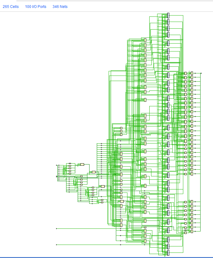
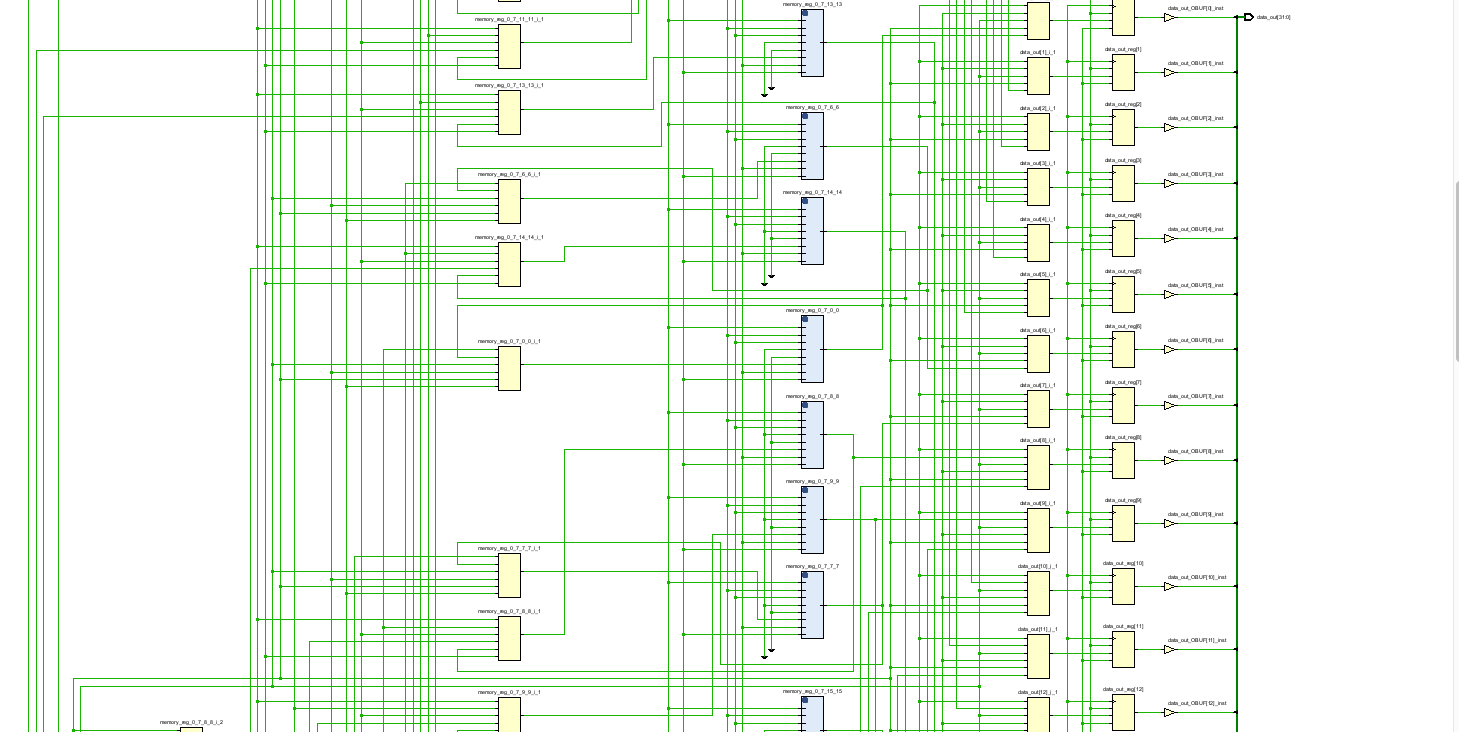
This one looks better:

enter image description here

enter image description here

enter image description here

As you can see, the synthezis used RAM blocks, hiding the complexity of the design inside them.

The design is probably much more efficient because it makes use of hardware features of a FPGA.

Unfortunately this is against my goal which was to understand the inner mechanism of those RAM block. So for now the best design regarding my goal is the second one, but as you have seen it is still complex and uses a lot of gates.

So I'm wondering : can we do better and improve the second design without using those RAM blocks introduced in the third design ? Or is my design ok and it is expected and usual to get such complexity in a RAM hardware ?

EDIT : as suggested in comments, FPGAs are not very well suited for implementing memory circuits, explaining the results in synthesis.

As a last edit, for info here is the most optimized design I was able to come up with, I don't think there's much optimization that can be done on this one. The main change compared to the second design above is that I put the reading outside the process and made it combinatory, and replaced variables by signals.

Fourth and last design:

library IEEE;
use IEEE.STD_LOGIC_1164.ALL;
use IEEE.NUMERIC_STD.ALL;
use work.memory_package.all;
entity data_ram is
    port(
        clk             : in std_logic;
        addr            : in std_logic_vector(31 downto 0);
        access_width    : in MEMORY_ACCESS_WIDTH_t;
        write_enable    : in MEMORY_ACCESS_TYPE_t;
        data_in         : in std_logic_vector(31 downto 0);
        
        data_out        : out std_logic_vector(31 downto 0)
    );
end data_ram;
architecture Behavioral of data_ram is
    signal memory           : DATA_RAM_MEMORY_ARRAY_t := (others => ("00000000", "00000000", "00000000", "00000000"));    -- init RAM to 0 for simulation
    signal word_index       : integer := 0;
    signal halfword_index   : integer := 0;
    signal byte_index       : integer := 0;
begin
    word_index      <= to_integer(unsigned(addr(31 downto 2)));
    halfword_index  <= to_integer(unsigned(addr(1 downto 0) and "10"));
    byte_index      <= to_integer(unsigned(addr(1 downto 0)));
    
    
    -- reading
    data_out <= 
        -- forbidding unaligned access
        (others => '1') when word_index >= DATA_RAM_MEMORY_SIZE_WORDS 
                            or (access_width = MEMORY_ACCESS_WIDTH_HALFWORD and addr(0) = '1')
                            or (access_width = MEMORY_ACCESS_WIDTH_WORD and addr(1 downto 0) /= "00") else
                            
        -- 16-bit
        (31 downto 16 => '0') & memory(word_index, halfword_index+1) & memory(word_index, halfword_index)
            when access_width = MEMORY_ACCESS_WIDTH_HALFWORD else
        -- 32-bit
        memory(word_index, 3) & memory(word_index, 2) & memory(word_index, 1) & memory(word_index, 0)
            when access_width = MEMORY_ACCESS_WIDTH_WORD else
            
        -- 8-bit
        (31 downto 8 => '0') & memory(word_index, byte_index);


    -- writing
    process(clk)
    begin
        if rising_edge(clk) then
            if(word_index < DATA_RAM_MEMORY_SIZE_WORDS) then
                case access_width is
                    when MEMORY_ACCESS_WIDTH_HALFWORD =>    -- 16-bit
                        -- forbidding unaligned access
                        if addr(0) = '0' and write_enable = MEMORY_ACCESS_TYPE_WRITE then
                                memory(word_index, halfword_index) <= data_in(7 downto 0);
                                memory(word_index, halfword_index+1) <= data_in(15 downto 8);
                        end if;
                        
                    when MEMORY_ACCESS_WIDTH_WORD =>  -- 32-bit
                        -- forbidding unaligned access
                        if addr(1 downto 0) = "00" and write_enable = MEMORY_ACCESS_TYPE_WRITE then
                                memory(word_index, 0) <= data_in(7 downto 0);
                                memory(word_index, 1) <= data_in(15 downto 8);
                                memory(word_index, 2) <= data_in(23 downto 16);
                                memory(word_index, 3) <= data_in(31 downto 24);
                        end if;
                        
                    when others =>  -- 8-bit
                        if(write_enable = MEMORY_ACCESS_TYPE_WRITE) then
                            memory(word_index, byte_index) <= data_in(7 downto 0);
                        end if;
                end case;
            end if;
        end if;
        
    end process;
end Behavioral;

enter image description here

enter image description here

enter image description here

Of course for a real implementation on a FPGA, the third design is the one to use as it leverages the hardware blocks of the FPGA, resulting in a much more efficient circuit.

\$\endgroup\$
6
  • \$\begingroup\$ To get an idea on complexity, did you try to synthesize a much simpler design with only 8 bit data bus width? Some complexity might come from the necessary multiplexers because of your memory core organized as 8 bit data in contrast to the entity's 32 bit data. Please edit your question to add your results. \$\endgroup\$ Commented Aug 2 at 5:49
  • \$\begingroup\$ In the updated code the memory array has indices 0..5. Yet the read and write have index := to_integer(shift_left(unsigned(addr),2));. Which as far as I tell means that only indices 0 and 4 into the ``memory` array will be used. The synthesis probably recognises that, resulting in only two 32-bit memory indices being used which explains why only 64 FFs are used. Do you have a test bench to check the updated code functions as expected? \$\endgroup\$ Commented Aug 2 at 20:21
  • \$\begingroup\$ @ChesterGillon I made the fix, as you suspected it confused the synthesis but I don't understand why, shifting was supposed to make the RAM byte-addressable instead of word-addressable. Consider the signal "10100", shifting it by 2 is supposed to return index=5. Also I changed a bit the design so readings are refreshed after a writing, before readings were refreshed only when the addr signal was changing. \$\endgroup\$
    – wbs2422
    Commented Aug 2 at 21:18
  • \$\begingroup\$ @ChesterGillon I also added a testbench and its simulation result, some things look suspicious \$\endgroup\$
    – wbs2422
    Commented Aug 2 at 21:19
  • \$\begingroup\$ @busybee I made the simpler design and edited my question to include it. The architecture of the schematic is quite the same, the only difference consisting of fewer LUTs and wires used. Does it mean that this complexity is normal and unavoidable ? \$\endgroup\$
    – wbs2422
    Commented Aug 2 at 21:23

3 Answers 3

2
\$\begingroup\$

This answer is really a set of review comments on the posted coded, which is hopefully OK since the question asks What do you think about it?

  1. The memory signal is 6*4 bytes, which is 192 bits and matches the number of FF resources in the design. I.e. one FF for every bit in the memory which means the number of FF resources should scale linearly with a change in the size of the RAM model.

  2. As already noted in a comment from @thebusybee the memory is logically 32-bits wide but the memory signal width is 8-bits. This results in multiple consecutive byte indices (e.g. memory(index+3), memory(index+2), memory(index+1) and memory(index)) rather than slicing parts of a 32-bit wide memory location. Changing the memory signal to be 32-bits might allow the synthesis tool to simplify the number of LUTs by removing intermediate additions to the index variables.

  3. The resource utilisation report contains entries for BRAM and URAM so presumably are targeting a Xilinx FPGA which has Block RAM and UltraRAM. Currently the usage for BRAM and URAM is zero.

    With the current memory size of 24 bytes the number of LUTs is about twice the number of FFs. The majority of the LUTs are probably involved in the address decoding for the memory array. Without trying to synthesise the design with increasing depth of the memory signal I'm not sure how the number of LUTs required will scale.

    Potentially changing to use the built in BRAM and URAM could reduce the overall resource utilisation and allow a larger RAM model to fit in the target FPGA due to:

    • Not needing to use FFs for the data storage
    • Reduced number of LUTs for address decoding.
  4. There is no context to how the data_ram will be used, so consider adding a comment to the code to explain the rationale for :

    • The write process being synchronous.
    • The read process being is asynchronous, with purely combinatorial logic to generate data_out based upon the addr input.

    Since the addr is used for both writing and reading, perhaps RAM_NO_WRITE could be renamed to RAM_READ for clarification. If do change to use Block RAM or UltraRAM for the memory storage, as suggested above, the read process will probably need to change to be synchronous, i.e. use the clk input.

  5. W.r.t the following:

    In case of a 8-bit or 16-bit reading, this signal is padded with leading 0s to get the expected 32-bit output width

    I can't see where the padding is performed. E.g. the following which handles the RAM_WRITE_HALFWORD case doesn't seem to write zeros to memory(index+3) nor memory(index+2) which I think will leave those memory locations at their previous values:

             elsif (write_select = RAM_WRITE_HALFWORD) and (index <= (DATA_RAM_MEMORY_SIZE-2)) then
                 memory(index+1) <= data_in(15 downto 8);
                 memory(index) <= data_in(7 downto 0);
    

    I.e. think the above code should be:

             elsif (write_select = RAM_WRITE_HALFWORD) and (index <= (DATA_RAM_MEMORY_SIZE-2)) then
                 memory(index+3) <= (others => '0');
                 memory(index+2) <= (others => '0');
                 memory(index+1) <= data_in(15 downto 8);
                 memory(index) <= data_in(7 downto 0);
    
  6. The question doesn't seem to mention the maximum frequency the RAM model needs to operate at. That could affect the required complexity. E.g. the need to pipeline the design.

\$\endgroup\$
3
  • \$\begingroup\$ I will reply in comment because the question content becomes quite long and hard to read. 1) Ok, got it. 2) As you suggested, I made the change and put the result in the question. This is what we were discussing above. 3) For now I have not planned to use a FPGA, I planned to stop at the simulation stage for now. Also the idea was to write everything "from scratch" to understand the inner mechanism of a RAM. \$\endgroup\$
    – wbs2422
    Commented Aug 2 at 21:42
  • \$\begingroup\$ 4) The whole project is to design and simulate a CPU implementing the 32-bit RISCV ISA, hence the synchronous writing. I made the read process a synchronous because I made it this way for the ROM module, I thought it was ok to do the same for the RAM... Why is it required to be synchronous for the RAM but no for the ROM ? I guess that it is related to the fact that we can also write it. \$\endgroup\$
    – wbs2422
    Commented Aug 2 at 21:48
  • \$\begingroup\$ 5) You're right, I forgot to do the padding ... But it was meant for the data_out output when reading a single byte or two bytes only. The fact that some indexes are left untouched was intended to allow 8 and 16-bit writings, instead of being only able to write full words. \$\endgroup\$
    – wbs2422
    Commented Aug 2 at 21:49
1
\$\begingroup\$

These are the resources required for such design:

If you want your code to synthesize to block-rams, then you have to use an idiom that the synthesizer recognises and which at least somewhat matches the capabilities of the block-rams on your chip.

If the synthesis tool can't map your design to a block-ram it will likely to to build it out of normal logic instead. This seems to be what has happened with your design.

it doesn't even contain enough flip-flops to store the 6 32-bit words

My experience is that when something synthesizes to something much smaller than it should be it's usually something along the lines of

  • I forgot to actually connect an input or output or clock line.
  • Something that should be a word wide is only a single bit wide.
  • There is a logic bug somewhere that stops any actual data passing through.

HDL optimisers can be very aggressive, they will remove huge swathes of logic if it's input OR output is not connected to anything.

\$\endgroup\$
2
  • \$\begingroup\$ Hi, you're right, it's probably due to the HDL optimization. I don't know why but shifting the addr signal by 2 confused the synthesis. The goal of this shift was to get a byte-addressable RAM instead of a word-addressable. I really don't understand what is the issue with that, for me it should work. Obviously it does not... \$\endgroup\$
    – wbs2422
    Commented Aug 2 at 21:26
  • \$\begingroup\$ Also, I don't intend to use a FPGA, I planned to stop at the simulation stage for now. The goal was to do everything "from scratch" to understand the inner working of a RAM, without the help of FPGA hardwares. \$\endgroup\$
    – wbs2422
    Commented Aug 2 at 21:30
1
\$\begingroup\$

You have thoroughly confused the synthesizer by indexing your memory by bytes, even though you only allow word-aligned reads and writes. To be honest, it confused me too at first, before I noticed that you were forcing the two LSBs of index to be zero before using it. Since the synthesizer didn't take this into account, it produced all of the logic to add small integers to index to access the memory array, and it also generated all of the input and output multiplexers to steer the input and output data bytes to the correct lanes of their respective buses.

Instead, start by declaring your memory to be 32 bits wide:

package program_content is
  constant DATA_RAM_MEMORY_SIZE : integer := 6;     -- in words
  type DATA_RAM_MEMORY_ARRAY_t is array(0 to DATA_RAM_MEMORY_SIZE-1)
                                  of std_logic_vector(31 downto 0);
end package program_content;

and then do the reads and writes as you described:

architecture Behavioral of data_ram is
  signal memory : DATA_RAM_MEMORY_ARRAY_t;
  signal index  : integer; 
begin
   
  -- coerce all addresses to word boundaries
  index := to_integer(unsigned(addr))/4;

  -- Reading
  process(addr)
  begin
    if index < DATA_RAM_MEMORY_SIZE then
      data_out <= memory(index);
    else
      data_out <= (others => '1');
    end if;
  end process;

  -- Writing
  process(clk, rst)
  begin
    if rising_edge(clk) then
      if index < DATA_RAM_MEMORY_SIZE then
        if (write_select = RAM_WRITE_BYTE) then
          memory(index) <= data_in and X"000000FF";
        elsif (write_select = RAM_WRITE_HALFWORD) then
          memory(index) <= data_in and X"0000FFFF";
        elsif (write_select = RAM_WRITE_WORD) then
          memory(index) <= data_in;
        end if;
      end if;
    end if;
  end process;
    
end Behavioral;

EDIT: You want to be able to write bytes at byte addresses and half words at half-word addresses. That's doable, but now we need to make the memory byte addressable, but still organized as words.

package program_content is
  -- Memory organized as words, but byte addressable
  constant DATA_RAM_MEMORY_SIZE : integer := 6;     -- in words
  type DATA_RAM_MEMORY_ARRAY_t is array (0 to DATA_RAM_MEMORY_SIZE-1, 3 downto 0)
                                  of std_logic_vector(7 downto 0);
end package program_content;

The module logic then looks like this:

architecture Behavioral of data_ram is
  signal memory : DATA_RAM_MEMORY_ARRAY_t;
  signal index  : integer; 
  signal hword  : integer; 
  signal byte   : integer; 
begin
   
  -- coerce all addresses to word boundaries
  index <= to_integer(unsigned(addr(31 downto 2)));
  hword <= to_integer(unsigned(addr(1 downto 0) and "10"));
  byte <= to_integer(unsigned(addr(1 downto 0)));

  -- Reading
  process (addr)
  begin
    if index < DATA_RAM_MEMORY_SIZE then
      data_out <= memory (index, 3)
                & memory (index, 2)
                & memory (index, 1)
                & memory (index, 0);
    else
      data_out <= (others => '1');
    end if;
  end process;

  -- Writing
  process (clk)
  begin
    if rising_edge(clk) then
      if index < DATA_RAM_MEMORY_SIZE then
        if (write_select = RAM_WRITE_BYTE) then
          memory (index, byte) <= data_in (7 downto 0);
        elsif (write_select = RAM_WRITE_HALFWORD) then
          memory(index, hword+1) <= data_in (15 downto 8);
          memory(index, hword) <= data_in (7 downto 0);
        elsif (write_select = RAM_WRITE_WORD) then
          memory(index, 3) <= data_in (31 downto 24);
          memory(index, 2) <= data_in (23 downto 16);
          memory(index, 1) <= data_in (15 downto 8);
          memory(index, 0) <= data_in (7 downto 0);
        end if;
      end if;
    end if;
  end process;
    
end Behavioral;
\$\endgroup\$
11
  • \$\begingroup\$ Thank you for your code suggestion. Here we write the entire data_in signal. Is there a way to add byte and halfword writings ? I've been thinking about concatenation: let's take as an example the writing of a byte at the 3rd location of the word: memory(index) <= memory(index)(31 downto 24) & data_in(23 downto 16) & memory(index)(15 downto 0) \$\endgroup\$
    – wbs2422
    Commented Aug 2 at 19:40
  • 1
    \$\begingroup\$ See edit above. \$\endgroup\$
    – Dave Tweed
    Commented Aug 2 at 21:37
  • 1
    \$\begingroup\$ And BTW, note that I did away with the global reset. Having that guarantees that you cannot use BRAM for the memory array. \$\endgroup\$
    – Dave Tweed
    Commented Aug 2 at 21:39
  • \$\begingroup\$ I am getting simulation issues "A fatal run-time error was detected. Simulation cannot continue.". Running it step-by-step shows that it's triggered on the very first access to the memory. I suspect it comes from an unexpected init value of the index signal. I had this issue previously, the init value of the index signal was negative, hence the test (index < DATA_RAM_MEMORY_SIZE) passed and the module tried to read an unexisting location. I solved it by changing signals to variable, it's why I had to use a process also for the reading. I'll investigate tomorrow and let you know. Thanks \$\endgroup\$
    – wbs2422
    Commented Aug 2 at 22:40
  • \$\begingroup\$ as I suspected this issue was resolved by using variables in a process. With this code I got results similar to those I've got with the original design. Perhaps they are inherent to a RAM design and should be expected instead of considered as "over-complicated" like I did. I tried a new design and it happens that the synthesis mapped it to RAM blocks, that is probably much more efficient for a practical implementation on a FPGA. But my goal was to understand what's inside these RAM blocks and to design one from scratch... I put the design and info in a new edit. What do you think ? \$\endgroup\$
    – wbs2422
    Commented Aug 3 at 17:29

Your Answer

By clicking “Post Your Answer”, you agree to our terms of service and acknowledge you have read our privacy policy.

Not the answer you're looking for? Browse other questions tagged or ask your own question.