0
\$\begingroup\$

There are so much hype and concern over metastability in cross clock domain. If the goal as an ASIC/FPGA designer is to ensure that the signal in source clock get propagated to destination clock even with metastability, consider the case below.

Suppose the input pulse or window signal into the synchronizer is stretched long enough to get latched by the destination clock of the synchronizer FFs twice or more, this ensures that setup & hold are met when the same signal which has been asserted get latched by the same FF 2nd time around; thus the circuit may experience metastability on leading edge of the input signal but the signal will make it out of FF of destination clk. The question is if I can ensure that this happens, do I even need synchronizer FFs (double FFs)? Wouldn't a single FF be sufficient? I guess it depends on what one needs to do with the signal after FF. If I create pulse based on trailing edge signal out of a destination clocked FF, that would work and I would not need to be concerned over whether the circuit experienced metastable condition or not.

\$\endgroup\$
1
  • 1
    \$\begingroup\$ No you need at least two sync flip-flops in the chain where the first flop is almost always metastable while the second one is not. And this depends on clock frequency, if you are working at higher frequencies like GHz, pretty sure you need MORE THAN just two flip-flops to achieve better MTBF at the destination clock domain. \$\endgroup\$
    – Mitu Raj
    Commented Jul 1, 2021 at 6:36

4 Answers 4

2
\$\begingroup\$

How can you guarantee that the hold time requirement of the receiving flip-flop will be met at the end of your wide pulse?

You still need at least two synchronizing flip-flops, I think.

\$\endgroup\$
2
\$\begingroup\$

The issue is that the length of time for a metastable flop to resolve could be longer than even your proposed 3x interval. Sure, a metastability event at 3x the clock period will be statistically rarer than if the clock were 1x or 2x, but it will never be zero.

Intel has a useful introductory paper on metastability, here: https://www.intel.com/content/dam/www/programmable/us/en/pdfs/literature/wp/wp-01082-quartus-ii-metastability.pdf

\$\endgroup\$
2
  • \$\begingroup\$ The paper is helpful info; based on this paper, it says that "In both cases, the output transition to a defined 1 or 0 state is delayed beyond the register’s specified tCO." tCO is significantly smaller than any clock period. Thus extra settling time is not a big issue here. If you extend the input long enough (3x or even 2x of clk period), it is guaranteed to get at least one solid latching of input without violation of setup & hold time. \$\endgroup\$
    – Dan Man
    Commented Jun 11, 2021 at 7:06
  • \$\begingroup\$ You misunderstand. The definition of metastable is that the flop doesn't resolve its state in the tCO period. It sticks somewhere in the middle for a while, until it gets a shove one way or another (from noise for example.) The statistical distribution will be that longer 'stuck' periods will be rarer than short ones. That's why slower clocks have higher MTBF figures. But make no mistake: if there's metastables happening, MTBF will never be infinity: there will always be failures. The dual-flop approach reduces the probability (increases MTBF) enough that it isn't a concern. \$\endgroup\$ Commented Jun 11, 2021 at 7:46
1
\$\begingroup\$

Looking at this from a qualitative standpoint...

The thing with metastability and its effects is that it is fairly linear with respect to source and destination clock frequencies, but highly non-linear with respect to the setup and hold times and the resolve time of the destination flip flop (highly process/speed dependent).

Say you have a semiconductor process that resolves a metastability condition in 100 ps, and has a setup and hold time of 1 ns. If the source and destinations clocks are 100 Hz and asynchronous wrt one another, the likelyhood of being affected by a metastability event is, very small (though not zero).

On the other hand, if the source and destination clocks are 100 MHz, then the likelyhood of a metastable event occurring at the receiving FF is very much greater, as the equations in the Intel paper hacktastical referenced indicate.

\$\endgroup\$
0
\$\begingroup\$

(I'll stick with DFFs and use FPGAs as the example...)

When a DFF in clock domain B (cdB) is driven by a DFF in clock domain A (cdA), the cdB DFF can go metastable if its setup/hold times are not met i.e. the input changes when the cdB clock is changing. You know that already.
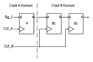
enter image description here

Internally, the circuit of each DFF has a very high gain and uses positive feedback. It doesn't stay perfectly balanced in the metastable state - it quickly heads towards one of the rails, into a stable 0 or 1.

Let's now consider cdB DFF_B1 driving a combinatorial circuit that goes into further DFFs. While cdB DFF_B1 output isn't outputting a true 0/1 voltage, the driven combinatorial circuits can also produce invalid or incorrect outputs. When cdB DFF_B1 recovers sufficiently, that combinatorial circuit can correct itself but that circuit's output DFFs may be clocked before it does. The likelihood of that depends on the exact circuit, parts used and the clock frequency.

There are two functions of the second DFF (DFF_B2) in a 2-stage domain input shift register:

(1) When DFF_B1 is clocked and goes from stable into metastable, DFF_B2 will have a whole clock period before it latches in the was-metastable value. In that time, the DFF_B1 output will have headed towards a supply rail and partly/entirely resolved itself. DFF_B2 has a better input voltage to sample and itself resolve.

(2) The DFF_B1 metastable voltage reaches only one further input: DFF_B2's. It doesn't drive any combinatorial logic that can cause the problem detailed above.

So the cdB DFF_B2 is necessary unless the final circuit is simple/slow-clocked enough. I have seen a circuit pass aerospace inspection with only one domain input DFF because it had simple gating and ran at 1 MHz. (It was only found once in the field, otherwise it would have been given two DFFs.)

It's also one of the factors I use when selecting the lowest clock frequency I can be sure of for a digital circuit.

For FPGAs, the DFF recovery time is usually specified in part reliability specifications (haven't checked all manfs but Xilinx/Altera do).

Last time I checked recent families, it was sub-1 ns. This is much shorter than a clock period at the part's maximum clock frequencies (see datasheets).

\$\endgroup\$

Your Answer

By clicking “Post Your Answer”, you agree to our terms of service and acknowledge you have read our privacy policy.

Not the answer you're looking for? Browse other questions tagged or ask your own question.