0
\$\begingroup\$

enter image description here

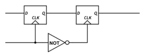
The above circuit is a master slave flip flop. Edge triggered. The working should be:

  1. During positive cycle, master is enabled by clock, storing data.
  2. At the negative edge (transition), slave takes the input and propagates it to Q.
  3. Even if any changes in D occur during the negative half, nothing is reflected in Q.

If D changes during the positive half, after the edge, won't that be stored in the first flip flop, and then propagated to the next flip flop, during negative half? Assuming the clock to Q time is considerably less than the positive cycle of the clock?

Suppose the nomenclature is D1,Q1 for first latch and D0,Q0 for second latch. Initial values: Q0=0, Q1=1

In positive half, at the edge, D1=1 occurs (assuming we want to store Q0=1), and thus Q1=1. If halfway through, D1 becomes 0 (say), then Q1=0 (within positive half). Then in the negative half, Q0 = 0. But the intention was to store 1 in Q0.

However, in edge triggering, we need to store only the value which is appears at the edge (positive in this case). Doesn't this change (D: 1->0 ) during the positive half contradict the whole concept of edge triggering? I am very confused.

The only thing I noticed here is that the propagation in second flip flop occurs at the negative edge, and any changes during the negative cycle is not propagated immediately.

\$\endgroup\$

2 Answers 2

1
\$\begingroup\$

The circuit you show is a negative edge-triggered register, not positive edge. It's perfectly OK for the output of the first latch to change while the clock is high; the point is that its output "freezes" at the negative edge, and this is the value that is propagated to the second latch.

So, while the clock is low, the second latch is passing the output of the first latch. But when the clock goes high again, the second latch also freezes, and the first latch is free to follow the input.

\$\endgroup\$
2
  • \$\begingroup\$ Okay, so if we switch the position of the inverter, so that it becomes a positive edge triggered register, then any changes during the negative clock cycle is fine, so long as the final value is updated at the positive clock edge, and any further changes during this time is not reflected in the final output. Is this correct? \$\endgroup\$
    – DaveFenner
    Commented Oct 10, 2023 at 12:17
  • \$\begingroup\$ Yes, swapping the connections between the inverter and the latch enables will have that effect. \$\endgroup\$
    – Dave Tweed
    Commented Oct 10, 2023 at 12:21
-1
\$\begingroup\$

It may be useful to first consider the behavior of a single edge triggered D-Flip-Flop in isolation.

schematic

simulate this circuit – Schematic created using CircuitLab

Because the Flip-Flop is edge triggered (which we know from the triangle at the CLK input) only the value of the D input present at the time of a low to high transition of CLK is registered. Each FF has set-up and hold times that the data is required to meet to be registered properly on a rising edge of CLK. However, changes to the D input outside of the set-up / hold-time range are not registered. This can be seen in the following input/output behavior.

enter image description here

enter image description here

enter image description here

Only the data that is present at the D input at times 30 usec, 530 usec and 1030 usec, are registered.

If D changes during the positive half, after the edge, won't that be stored in the first flip flop, and then propagated to the next flip flop, during negative half? Assuming the clock to Q time is considerably less than the positive cycle of the clock?

No. The little triangle in the symbol for the master flip-flop indicates that that it is edge triggered. Therefore, the data input may change without affecting the state of the flip-flop provided the data input change is not "near" a clock transition. By not "near", I mean that the data input change occurs outside of the set-up and hold times of the flip-flop.

\$\endgroup\$
2
  • \$\begingroup\$ You're reading too much into the OP's schematic diagram. CircuitLab does not have a separate symbol for "D latch" vs. "edge-triggered DFF". The text is clearly describing these boxes as latches. \$\endgroup\$
    – Dave Tweed
    Commented Oct 10, 2023 at 15:13
  • \$\begingroup\$ @DaveTweed No. The OP's circuit was taken from my answer to a previous question. The poster is confused about that answer. \$\endgroup\$ Commented Oct 10, 2023 at 16:06

Your Answer

By clicking “Post Your Answer”, you agree to our terms of service and acknowledge you have read our privacy policy.

Not the answer you're looking for? Browse other questions tagged or ask your own question.